


En esta entrada vamos a tratar los principios básicos de una red segmentada por VLANS mediante la herramienta de Cisco packet tracer.
Sin duda se trata de una herramienta muy poderosa, con la cual se puede reproducir muy fielmente un entorno de redes. Empecemos por el principio. Para poder descargarnos la herramienta, primeramente deberemos subscribirnos en la página de Network Academy de Cisco. Podréis acceder mediante el siguiente enlace. Una vez registrado ya nos podremos descargar el software y realizar algunos cursos disponibles.
El planteamiento que se va a seguir en esta entrada es el siguiente:
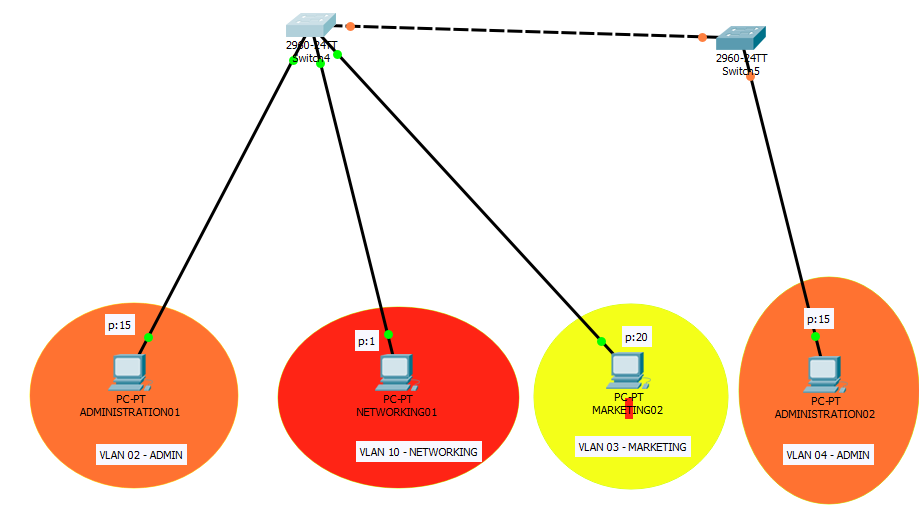
- Dos switch con un enlace trunk entre ellos.
- Tres VLANS.
- VLAN 02 – ADMIN
- VLAN 10 – NETWORKING
- VLAN 03 – MARKETING
- Cuatro equipos correspondientemente.
Y las reglas que se cumplirán entre las VLANS serán las siguientes:
- La VLAN 02 podrá ver a la VLAN 03
- La VLAN 10 podrá ver a todas las VLANS.
El siwtch01 contará con la siguiente configuración, primeramente la creación de las VLANS:
Switch>enable
Switch#configure terminal
Enter configuration commands, one per line. End with CNTL/Z.
Switch(config)#vlan 02
Switch(config-vlan)#name VLANADMIN
Switch(config-vlan)#exit
Switch(config)#vlan 03
Switch(config-vlan)#name VLANMARKETING
Switch(config-vlan)#exit
Switch(config)#vlan 10
Switch(config-vlan)#name VLANNETWORKING
Switch(config-vlan)#exi
Switch 02:
Switch>enable
Switch#configure terminal
Enter configuration commands, one per line. End with CNTL/Z.
Switch(config)#vlan 02
Switch(config-vlan)#name VLANADMIN
Switch(config-vlan)#exit
Ahora que ya tenemos las VLANS creadas, deberemos asignarlas a los puertos o rangos de puertos que queramos:
Switch 01:
Switch>enable
Switch#configure terminal
Enter configuration commands, one per line. End with CNTL/Z.
Switch(config)#interface range f0/15-19
Switch(config-if-range)#switchport mode access
Switch(config-if-range)#switchport access vlan 02
Switch(config-if-range)#exit
Switch(config)#interface range f0/01
Switch(config-if-range)#switchport mode access
Switch(config-if-range)#switchport access vlan 10
Switch(config-if-range)#exit
Switch(config)#interface range f0/20-24
Switch(config-if-range)#switchport mode access
Switch(config-if-range)#switchport access vlan 03
Switch(config-if-range)#exit
Switch 02:
Switch>enable
Switch#configure terminal
Enter configuration commands, one per line. End with CNTL/Z.
Switch(config)# interface range f0/15-19
Switch(config-if-range)#switchport mode access
Switch(config-if-range)#switchport access vlan 02
Switch(config-if-range)#exit
Bien ahora si hacemos un show vlan en el switch 01, veremos que ya tenemos las vlans asignadas a los puertos:
Switch>show vlan

VLAN Name Status Ports
---- -------------------------------- --------- -------------------------------
1 default active Fa0/2, Fa0/3, Fa0/4, Fa0/5
Fa0/6, Fa0/7, Fa0/8, Fa0/9
Fa0/10, Fa0/11, Fa0/12, Fa0/13
Fa0/14, Gig0/1, Gig0/2
2 VLANADMIN active Fa0/15, Fa0/16, Fa0/17, Fa0/18
Fa0/19
3 VLANMARKETING active Fa0/20, Fa0/21, Fa0/22, Fa0/23
Fa0/24
10 VLANNETWORKING active Fa0/1
1002 fddi-default active
1003 token-ring-default active
1004 fddinet-default active
1005 trnet-default active

VLAN Type SAID MTU Parent RingNo BridgeNo Stp BrdgMode Trans1 Trans2
---- ----- ---------- ----- ------ ------ -------- ---- -------- ------ ------
1 enet 100001 1500 - - - - - 0 0
2 enet 100002 1500 - - - - - 0 0
3 enet 100003 1500 - - - - - 0 0
10 enet 100010 1500 - - - - - 0 0
1002 fddi 101002 1500 - - - - - 0 0
1003 tr 101003 1500 - - - - - 0 0
1004 fdnet 101004 1500 - - - ieee - 0 0
1005 trnet 101005 1500 - - - ibm - 0 0

VLAN Type SAID MTU Parent RingNo BridgeNo Stp BrdgMode Trans1 Trans2
---- ----- ---------- ----- ------ ------ -------- ---- -------- ------ ------

Remote SPAN VLANs
------------------------------------------------------------------------------

Primary Secondary Type Ports
------- --------- ----------------- ------------------------------------------
Switch>
El siguiente paso será establecer el modo trunk entre los dos switches.
Switch 01:
Switch>enable
Switch#configure terminal
Enter configuration commands, one per line. End with CNTL/Z.
Switch(config)#interface range g0/02
Switch(config-if-range)#switchport mode trunk

Switch(config-if-range)#
%LINEPROTO-5-UPDOWN: Line protocol on Interface GigabitEthernet0/2, changed state to down

%LINEPROTO-5-UPDOWN: Line protocol on Interface GigabitEthernet0/2, changed state to up

Switch(config-if-range)#exit
Switch 02:
Switch>enable
Switch#configure terminal
Enter configuration commands, one per line. End with CNTL/Z.
Switch(config)#interface range g0/02
Switch(config-if-range)#switchport mode trunk
Switch(config-if-range)#exit
En este punto si hacemos un ping entre la VLAN 02 de un extremo al otro, podremos comprobar que llegará, no sucederá lo mismo si lo hacemos al resto de VLANS. Esto es debido a que no tenemos todavía configurado el routing entre VLANS
Ahora tendremos que configurar el switch01 y el router:
switch01
Switch>enable
Switch#configure terminal
Enter configuration commands, one per line. End with CNTL/Z.
Switch(config)#interface g0/01
Switch(config-if)#switchport mode trunk
Switch(config-if)#exit
router
Router>enable
Router#configure terminal
Enter configuration commands, one per line. End with CNTL/Z.
Router(config)#interface g0/0
Router(config-if)#no shutdown

Router(config-if)#
%LINK-5-CHANGED: Interface GigabitEthernet0/0, changed state to up

%LINEPROTO-5-UPDOWN: Line protocol on Interface GigabitEthernet0/0, changed state to up

Router(config-if)#exit
Ahora establecemos la configuración de las VLANS:
Router>enable
Router#configure terminal
Enter configuration commands, one per line. End with CNTL/Z.
Router(config)#interface g0/0.2
Router(config-subif)#
%LINK-5-CHANGED: Interface GigabitEthernet0/0.2, changed state to up

%LINEPROTO-5-UPDOWN: Line protocol on Interface GigabitEthernet0/0.2, changed state to up
encapsulation dot1q 2
Router(config-subif)#ip address 192.168.1.1 255.255.255.0
Router(config-subif)#exit
Router(config)#interface g0/0.3
Router(config-subif)#
%LINK-5-CHANGED: Interface GigabitEthernet0/0.3, changed state to up

%LINEPROTO-5-UPDOWN: Line protocol on Interface GigabitEthernet0/0.3, changed state to up
encapsulation dot1q 3
Router(config-subif)#ip address 192.168.3.1 255.255.255.0
Router(config-subif)#exit
Router(config)#interface g0/0.10
Router(config-subif)#
%LINK-5-CHANGED: Interface GigabitEthernet0/0.10, changed state to up

%LINEPROTO-5-UPDOWN: Line protocol on Interface GigabitEthernet0/0.10, changed state to up
encapsulation dot1q 10
Router(config-subif)#ip address 192.168.10.1 255.255.255.0
Router(config-subif)#exit
Llegados a este punto si tenemos los equipos configurados correctamentes con sus ips y gateways la comunicación fluirá en todas las direcciones y VLANS, una vez hecho, lo podemos comprobar mediante pings, ahora lo único que falta es accer nuestros access list para restringir los accesos entre VLANS no deseadas.
Esta tarea os la dejo pendiente para vosotros!.
Hasta la próxima!.


